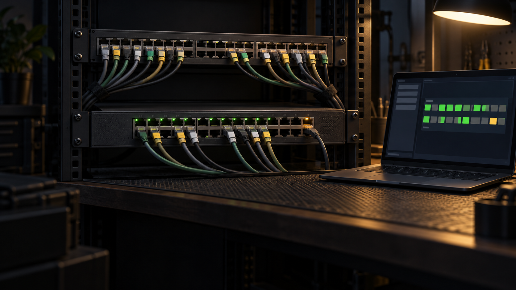
A switch port map should answer a practical question without opening the rack: what is connected to this port, how is the port configured, and what test would show that the connection still works? A row containing only a device name and port number cannot do that. Useful maps connect the physical cable, learned network evidence, intended configuration, and the service that depends on the link.
Build the first version from the switch and the rack, then keep it current as part of ordinary maintenance. The goal is not a perfect diagram. It is a record that makes an unplugged cable, a VLAN change, or an unknown device easier to investigate.
Choose a format that remains usable
Use one row per physical port, including ports that are disabled, empty, or reserved. A spreadsheet works well for a small lab because it can be filtered by VLAN, device, or review date. A version-controlled text file is also reasonable if everyone who maintains the network can edit it. Store the map with the rest of the records described in the home lab documentation checklist, not only on a laptop that might be unavailable during an outage.
Start with these fields: switch name, switch hardware identity, port, physical label, connected device, remote port, purpose, link state, negotiated speed, native VLAN, tagged VLANs, PoE setting, aggregation group, source of the evidence, last verification date, and notes. Add a location when the cable leaves the rack. Separate intended configuration from observed state so a temporary mismatch stays visible.
| Field | What it records | Useful evidence |
|---|---|---|
| Physical identity | Switch, local port, cable label, remote endpoint | Rack inspection and labels |
| Logical role | Purpose, native VLAN, tagged VLANs, aggregation | Saved or running configuration |
| Observed state | Link, speed, learned MAC addresses, neighbor | Switch status, MAC address table, LLDP |
| Power and test | PoE setting, dependent service, verification result | Port power view and a service check |
Begin with the cable and the port
Stand in front of the switch and compare every used port with its cable. Record the printed port identifier exactly as the platform presents it. Add a durable physical label near both cable ends before relying on a color or memory. The rack cable-labeling checklist covers label placement and naming. The switch map should reference that cable identity instead of creating a second naming system.
Do not unplug a cable merely to learn where it goes. Trace it visually when possible, check the far-end label, and use the switch evidence in the next steps. If a cable disappears into a wall, patch panel, or bundle, record the intermediate port as well as the final room or device. Mark uncertain results as unknown. A visible gap is safer than a confident guess.
Use interface state and learned addresses carefully
Capture the switch’s interface status, description, negotiated speed, and error counters. Cisco documents separate commands for interface status, descriptions, counters, and Layer 2 switchport state. Other vendors expose similar information through a controller or management page. Record the command, export, or screen that supplied each field so the map can be refreshed later.
Next, inspect the MAC address table. Cisco’s address-table command can filter results by interface, VLAN, or address and reports the VLAN, learned address, port, and entry type. A single learned address can support a device hypothesis, especially when it matches an inventory record. It is not proof by itself.
An access point, another switch, a virtualization host, or a bridge may place several MAC addresses behind one physical port. A sleeping endpoint may have no current dynamic entry. An uplink can contain addresses from much of the network. Record all relevant observations, but label the connected device from corroborating evidence such as the cable, device inventory, DHCP records, or neighbor discovery.
Add LLDP data without treating silence as an answer
LLDP can make a port map much more specific. Cisco’s current documentation says LLDP exchanges information on a port-by-port basis. Its neighbor summary can show the local interface, device ID, and remote port ID. Detailed output may add a system name, description, capabilities, management address, and other advertised fields.
Copy the useful neighbor details into the map and record that LLDP supplied them. The data is advertised by the neighbor, so it can be incomplete, disabled, stale until its hold time expires, or absent on an ordinary endpoint. No LLDP entry does not mean that a port is unused. Check link state, traffic, the MAC address table, the physical cable, and the dependent service before deciding what the port does.
The managed-switch guide explains why these inspection features are useful even in a small network. Keep discovery enabled only where it fits the security and operational policy for the lab.
Record configuration and power separately
A correct endpoint name does not make the port configuration correct. Record whether the port is enabled, its access or trunk role, native VLAN, tagged VLAN allowance, speed setting, isolation policy, mirroring state, aggregation membership, and spanning-tree controls that differ from the switch default. Ubiquiti’s current switch-settings guide lists native VLAN, tagged VLAN management, PoE, link speed, isolation, mirroring, and aggregation among the settings that can vary by port.
Give PoE its own fields. Record whether power is enabled, the device that depends on it, and any configured port limit. Do not turn an observed idle draw into a universal device requirement. The port map is an inventory, not a power-budget calculation. If a phone, access point, camera, or other endpoint needs PoE to start, make that dependency visible before a cable move.
Verify the map and keep it alive
Review the completed rows from both directions. Starting at a port, confirm that the cable and endpoint match the record. Starting with an important service, identify every switch port and uplink it needs. Test actual service behavior where practical. A green link light does not confirm DHCP, DNS, routing, VLAN membership, storage access, wireless service, or management reachability.
Resolve contradictions while the context is available. A cable label that disagrees with LLDP may indicate an old label, a moved device, or a neighbor name that was never updated. A learned MAC address on an unexpected VLAN may expose a port-profile mistake. Write the reason for the final identification and keep the raw export when it helps future review.
Update the map after port changes, switch configuration work, device moves, and cable replacement. Give each row a verification date and review the map before the next home lab maintenance window. Retain an older version so an unexplained change can be compared with the prior known state.
A useful switch port map is modest evidence collected consistently. Physical labels show where a cable goes. Interface state shows what the switch sees now. The MAC address table and LLDP add clues. Configuration records explain what the port is meant to do. Service verification closes the loop.
Sources
- Cisco Configure LLDP
- Cisco Business address table commands
- Cisco IOS Virtual Switch Command Reference
- Ubiquiti UniFi switch settings
Current manufacturer documentation was reviewed November 2, 2026. This is documentation-based guidance. It does not claim that LabGremlin discovered, mapped, configured, tested, or validated a specific switch, cable, controller, endpoint, or network.